
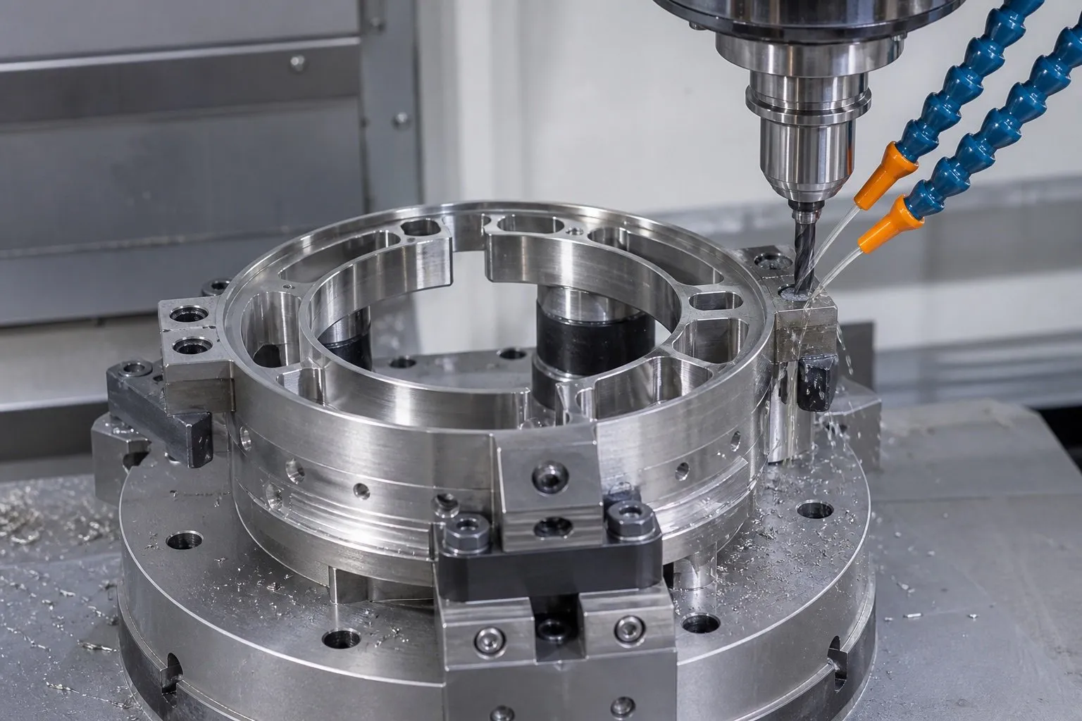
304 stainless steel is widely used for corrosion-resistant housings, medical-equipment components, fluid-handling parts and precision fixtures. It is also a demanding material when the design includes thin walls, broad flat surfaces, deep pockets or slender features. A part may meet size while clamped and then move after unclamping, cooling or final material removal.
Successful 304 stainless steel CNC machining therefore depends on controlling the whole process. Raw-material stress, work hardening, cutting heat and clamping force must be managed together. A fixed spindle-speed recipe cannot compensate for an unstable process plan.
Why 304 stainless steel parts distort
Work hardening increases cutting load
304 is an austenitic stainless steel with high ductility and a strong tendency to work harden. If the edge rubs instead of cutting a consistent chip, the surface becomes harder and the next pass generates more force and heat. Dwell marks, worn tools and an ineffective feed can quickly make the condition worse.
Heat remains concentrated near the cut
Heat leaves the cutting zone less readily than it does in many carbon steels. Local expansion during machining and contraction after cooling can shift size or flatness, especially when material is removed unevenly from opposite sides.
Material removal changes the stress balance
Plate, bar and prior manufacturing operations can contain residual stress. Removing a large volume from one area changes that balance. The result may be bow, twist or bore movement even when the machine tool repeats accurately.
Clamping can temporarily force the part into shape
A thin plate pressed flat against a fixture may measure correctly while restrained. When the clamps are released, elastic strain returns and the part changes shape. More clamping force is therefore not automatically more stable.
A stable machining sequence
A practical route for a tolerance-sensitive part is: verify stock and datum strategy; rough machine with balanced stock removal; allow the part and fixture to stabilize; semi-finish; release and re-establish the workholding; finish critical features; deburr; then inspect after unclamping at a controlled temperature.
Some parts benefit from an intermediate stabilization or stress-relief operation, but there is no universal temperature-and-time recipe for every 304 component. Material condition, geometry, corrosion requirements, dimensional tolerance and subsequent processing should be reviewed before adding thermal treatment.
Keep stock removal balanced
Begin with reasonably uniform machining allowance. For thin plates and open frames, remove material in stages and alternate sides where practical. Roughing should leave enough material to restore datums and remove the affected surface during finishing, without leaving so much stock that the finish pass creates a large force.
Separate roughing and finishing logically. After heavy material removal, let the workpiece and fixture reach a stable temperature before final cuts. For critical components, inspect the semi-finished part in a released condition so that movement is discovered before the last operation.
Use low-distortion workholding
- Increase support area. Soft jaws, shaped nests, full-area backup plates and distributed clamps are preferable to concentrated point loads.
- Use only the force required. Clamping must resist the real cutting load without slip, but should not flatten or expand the component.
- Support thin bores carefully. A controlled-clearance mandrel or support ring can reduce deflection, but excessive interference can enlarge the bore.
- Plan a release-and-reclamp step. Before the final light pass, release stored clamping strain, re-seat the datum surfaces and verify the part again.
- Keep support predictable. Burrs, chips and inconsistent contact under the workpiece can introduce more error than the machine itself.
Select tools and cutting data from the real setup
RPM and feed rate should be calculated from cutting speed, tool diameter, flute count and feed per tooth. They also need to account for cutter geometry, tool grade, radial and axial engagement, overhang, coolant delivery and machine rigidity. For this reason, a statement such as “run 4,000 rpm and 500 mm/min” is not transferable between different tools and parts.
Start from the cutting-tool supplier’s recommendation for 304 or the relevant ISO M material group, then validate the first part by checking chip formation, cutting sound, tool wear, temperature and dimensional movement.
Tooling practices that reduce risk
- Use sharp carbide tools and edge geometries intended for austenitic stainless steel.
- Maintain a real chip load and avoid repeated rubbing or dwelling on the surface.
- Keep tool overhang as short as access allows.
- Use a smooth toolpath with lighter radial engagement when finishing flexible walls.
- Replace a worn finishing tool before it begins to push and polish the material.
- Deliver coolant consistently to the cutting edge and prioritize chip evacuation in deep holes and pockets.
Strategies for common part geometries
Thin plates and broad flat surfaces
Use a flat, clean support and distribute the holding force. Machine opposite sides in stages rather than removing nearly all stock from one face first. After unclamping, support the part consistently during inspection; otherwise the measurement method can hide or exaggerate flatness error.
Thin-wall frames and deep pockets
Where the design permits, keep temporary ribs or sacrificial bridges during heavy roughing and remove them late in the process. Progress from rigid regions toward flexible walls. In finishing, avoid abrupt engagement changes that can pull a thin corner away from the programmed path.
Bores and ring-shaped components
Finish critical bores after the external operations that are most likely to redistribute stress. Use stable chip evacuation and controlled support, then check diameter, roundness and concentricity after the part is released. An in-process probe reading under clamping force does not by itself confirm the free-state geometry.
Slender features
Reduce unsupported length whenever possible and plan the cut direction so force acts toward the support. Multiple light, consistent passes are generally easier to control than one heavy finishing pass, but the cut must remain productive enough to avoid rubbing and work hardening.
Inspection is part of distortion control
A robust inspection plan records when and how a dimension is measured. For a thin-wall 304 component, useful checkpoints include the rough-machined condition, semi-finished and unclamped condition, and final stabilized condition. Critical parts should be measured at a controlled temperature with a repeatable support method.
This sequence helps separate four different causes: machine or datum error, clamp-induced strain, thermal drift and residual-stress movement. Without those checkpoints, compensation changes may correct one part and make the next batch worse.
Common symptoms and likely process checks
- Flatness changes after unclamping: review support area, clamp force, balanced stock removal and the release-and-reclamp sequence.
- Bore becomes oval: review jaw pressure, wall support, bore finishing order and free-state inspection.
- Thin wall bows during the final pass: review cutter sharpness, radial engagement, toolpath direction and temporary support.
- Size drifts during the cycle: review coolant consistency, tool wear, part temperature and measurement timing.
- Burrs and smeared edges increase: review tool condition and whether the edge is cutting rather than rubbing.
Frequently asked questions
Can distortion in 304 stainless steel be eliminated completely?
No universal process can guarantee zero movement for every geometry and tolerance. The risk can be reduced substantially through balanced allowance, staged machining, low-force workholding, sharp tools, stable cooling and free-state inspection.
Should a thin-wall part be clamped as tightly as possible?
No. Excessive force can deform the part during machining and cause springback after release. The objective is sufficient resistance to cutting forces with broad, even support and minimal induced strain.
Can published speeds and feeds be copied directly?
They should be treated only as a starting point. Tool diameter, flute count, tool grade, engagement, overhang, coolant and machine rigidity all affect the correct values. Use the tool manufacturer’s data and validate it on the actual setup.
Build stability into the process
Reducing distortion in 304 stainless steel CNC machining is mainly a matter of controlling stress, heat and workholding. Uniform stock, balanced roughing, stable temperature, low-force fixturing, sharp tools and unclamped inspection form a more reliable solution than a single “best” speed or depth of cut.
HengDa provides precision CNC milling and prototyping services for stainless-steel components. Send the 3D model, 2D drawing, material condition, quantity, finish and critical tolerances through our contact page. Our team can review tool access, workholding and inspection requirements before production.