
Face milling is one of the most common operations for producing flat surfaces in CNC milling. It can clean and level raw stock, establish a datum for subsequent operations, or serve as a finishing process to improve part flatness and surface quality. The process is widely used for aluminum alloys, steel, stainless steel, cast iron, titanium alloys, and some engineering plastics.
Face milling results depend on much more than spindle speed. Cutter diameter, insert geometry, entering angle, feed per tooth, depth of cut, radial width of cut, workholding rigidity, and tool runout all affect machining stability. This guide explains how to plan a face milling operation by examining the process fundamentals, common types, cutter selection, and quality control.
What Is Face Milling?
Face milling is a milling process that uses a rotating cutter to machine a flat surface. During machining, the cutter axis is typically perpendicular to the target surface. Cuttng is performed primarily by the cutting edges near the face of the cutter, while the peripheral edges also contribute to material removal.
Unlike end milling, which is mainly used to machine sidewalls, slots, and contours, face milling is intended to produce broad, flat, and consistent surfaces efficiently. Common applications include:
- Removing rough outer layers from castings, forgings, or saw-cut stock
- Establishing a datum surface before drilling, slotting, or contour machining
- Machining mating, sealing, and assembly surfaces
- Improving flatness and surface roughness after roughing
- Preparing a uniform surface for subsequent grinding, coating, or other finishing processes
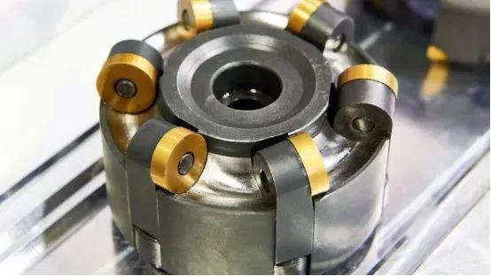
An indexable face mill uses multiple inserts to cut simultaneously, making it suitable for machining wide, flat surfaces.
How Does Face Milling Work?
A stable face milling process typically includes the following steps.
1. Establish Reliable Workholding
The workpiece must be adequately supported and securely located. Insufficient clamping force can cause vibration and movement, while excessive force may deform thin-walled parts or plates. Before machining, confirm that the fixture will not interfere with the cutter, toolholder, or chip evacuation path.
2. Select the Cutter for the Part and Machine
The cutter diameter, number of teeth, entering angle, and insert grade should match the workpiece width and material, as well as the machine’s power, spindle rigidity, and surface requirements. Indexable face mills are generally suitable for open surfaces. Cutters with an entering angle close to 90° may be required near sidewalls, while end mills can be used for smaller surfaces or localized areas.
3. Set the Toolpath and Cutting Parameters
The CNC program controls cutter entry, cutting, exit, and the overlap between passes. Roughing typically prioritizes stable material removal, while finishing places greater emphasis on tool runout, feed per tooth, depth of cut, and surface texture.
4. Control Chips and Heat
Chips left on the machined surface may be recut and scratch the part. Coolant, air blast, or other chip evacuation methods should be selected according to the workpiece material, insert grade, and cutter supplier’s recommendations. The same cooling strategy is not suitable for every material and cutting tool.
5. Inspect the Machined Part
After machining, inspect dimensions, flatness, parallelism, and surface roughness according to the drawing. If the part will undergo anodizing, coating, grinding, or assembly, also confirm whether downstream operations require machining allowance or protection for critical surfaces. These requirements should be coordinated with the selected CNC machining surface finish before production.
Common Types of Face Milling
Face milling operations can be classified by cutter entering angle, depth of cut, and machining objective.
| Type | Common Cutter Features | Primary Applications | Key Considerations |
|---|---|---|---|
| General-purpose face milling | Typically uses a 30°–60° entering angle, with 40°–45° being common | Roughing, semi-finishing, and establishing datum surfaces | Balance cutting forces, depth of cut, and surface quality |
| Near-90° face milling | Allows machining close to a vertical wall | Surfaces adjacent to shoulders, areas near fixtures, or locations with limited clearance | Produces higher radial cutting forces and requires sufficient rigidity |
| High-feed milling | Typically uses a small entering angle of about 10°–30° and a shallow depth of cut | Roughing at higher table feeds | Feed must be based on effective chip thickness and cutter data rather than a fixed rule |
| Heavy-duty face milling | Robust inserts, greater depths of cut, and a rigid cutter body | Large castings, forgings, or roughing with high material removal rates | Requires sufficient machine power, rigidity, and reliable chip evacuation |
| Face finishing | Finishing inserts, wiper inserts, or an adjustable cutter body | Improving flatness, surface texture, and surface roughness | Focus on axial runout, insert seating, and feed per tooth |

Different face mills are designed for general-purpose machining, high-feed milling, heavy-duty cutting, or finishing.
How to Choose a Face Mill
Indexable Face Mills
An indexable face mill holds multiple replaceable inserts in the cutter body and is a common choice for CNC machining. Individual inserts can be indexed or replaced when worn, making these cutters suitable for applications ranging from prototypes to production runs. Selection factors include insert grade, chipbreaker geometry, entering angle, pitch, and maximum allowable depth of cut.
Finishing Cutters With Wiper Inserts
Wiper inserts increase the contact area with the machined surface and can improve surface texture when tool runout and feed are properly controlled. However, a wiper edge cannot compensate for poor spindle condition, inconsistent insert seating, or workpiece vibration.
End Mills and Square Shoulder Mills
End mills or near-90° square shoulder mills provide greater flexibility when the surface is small, a shoulder must be machined at the same time, or the cutter must work close to a sidewall. Compared with a large-diameter face mill, these tools typically require more passes to cover a wide surface.
Fly Cutters
A fly cutter uses a single cutting edge to machine a flat surface and is commonly used on manual equipment or for repair and low-volume work. It can produce a uniform tool-mark pattern, but its material removal efficiency is generally lower than that of a multi-tooth face mill. It also places greater demands on cutter balance and operational safety.
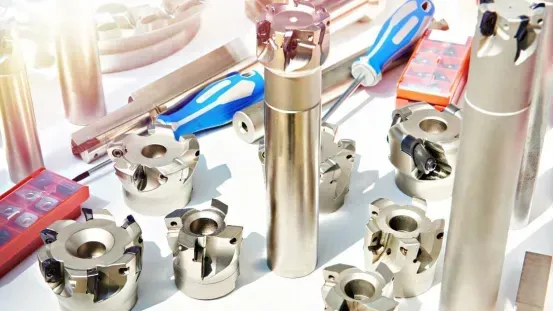
Cutter body diameter, pitch, insert geometry, and tool overhang should match the machine and part conditions.
Key Face Milling Parameters
Cutting Speed and Spindle Speed
Cutting speed should be selected according to the workpiece material, insert grade, cutter diameter, and cutter supplier’s data. Under metric conditions, spindle speed can be estimated as:
n = 1000 × Vc ÷ (π × D)
where n is spindle speed in revolutions per minute (r/min), Vc is cutting speed in meters per minute (m/min), and D is cutter diameter in millimeters (mm).
Feed per Tooth and Table Feed
Feed per tooth determines the chip load carried by each cutting edge. Table feed can be estimated as:
Vf = fz × z × n
where fz is feed per tooth in millimeters per tooth (mm/tooth), z is the effective number of teeth, n is spindle speed in revolutions per minute (r/min), and Vf is table feed in millimeters per minute (mm/min). A feed that is too low may cause rubbing, while an excessive feed may lead to insert chipping, vibration, or reduced surface quality.
Axial Depth of Cut and Radial Width of Cut
Axial depth of cut determines the thickness of material removed in one pass, while radial width of cut determines the cutter’s engagement with the workpiece. Both should be set according to machine power, tool overhang, workholding rigidity, and insert capability. Finishing typically uses a smaller depth of cut with a stable, uniform machining allowance.
Entering Angle
The entering angle changes both the direction of cutting forces and the effective chip thickness. A smaller entering angle produces a chip-thinning effect, making it suitable for shallow depths of cut and high table feeds. A cutter with an entering angle close to 90° can machine near a sidewall but generates greater radial force.
Cutter Position and Toolpath
The position of the cutter center relative to the workpiece affects entry, exit, cutting-force direction, and the resulting surface pattern. Avoid sudden, unstable entry and maintain smooth cutter engagement whenever possible. The specific offset and feed direction should be selected according to cutter diameter, workpiece width, and the cutter manufacturer’s recommendations.
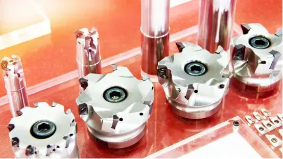
Consistent insert seating and controlled cutter body runout directly affect surface quality in multi-tooth face milling.
What Is the Difference Between Face Milling and End Milling?
| Comparison | Face Milling | End Milling |
|---|---|---|
| Primary objective | Machine broad, flat surfaces and establish datums | Machine sidewalls, slots, pockets, shoulders, and contours |
| Tool axis relative to the machined feature | Normal to the broad face being machined | Typically parallel to a sidewall and normal to a pocket floor |
| Primary cutting area | Cutting edges near the cutter face, with peripheral edges also engaged | Primarily the peripheral edges, with the end edges also able to cut |
| Common cutters | Indexable face mills, shell mills, and finishing mills | Square end, ball nose, corner radius, or square shoulder end mills |
| Typical applications | Leveling stock, datum surfaces, assembly surfaces, and finishing large flat areas | Slots, sidewalls, pockets, contours, and complex 3D surfaces |
The two processes are often used together on the same part. Face milling first establishes a stable datum, followed by drilling, slotting, contouring, or pocket machining.
Machining Considerations for Different Materials
- Aluminum alloys: Higher cutting speeds can often be used, but built-up edge, material adhesion, and surface scratching by chips must be prevented. Sharp inserts, effective chip evacuation, and stable workholding are important.
- Carbon and alloy steels: Parameters should be set according to hardness, heat-treatment condition, and insert grade. Avoid excessive tool overhang and unstable entry.
- Stainless steel: Because it is prone to work hardening and heat generation, avoid allowing the insert to rub against the surface. Maintain a stable chip load and use a suitable insert geometry.
- Cast iron: Surface scale and inclusions can cause impact loading and abrasive wear. Insert toughness, toolpath, and dust or chip control require separate consideration.
- Titanium and heat-resistant alloys: Low thermal conductivity and high temperatures in the cutting zone make these materials more sensitive to rigidity, insert grade, engagement strategy, and cutting data.
- Engineering plastics and composites: Use sharp tools and control heat. Thin sheets and laminated materials also need additional support to reduce deformation, burrs, or delamination.
Parameters must be validated for the actual material grade, tooling system, machine condition, and part geometry. Speeds and feeds from another project should not be applied without verification.
How to Improve Surface Quality in Face Milling
- Reduce tool overhang and increase system rigidity. Check the spindle, toolholder, cutter body, fixture, and workpiece for looseness or vibration.
- Clean the insert pockets and control axial runout. Chips, burrs, or variations in insert seating height can cause one insert to carry an excessive cutting load.
- Leave a uniform allowance for finishing. Uneven stock can cause cutting-force fluctuations that affect flatness and surface texture.
- Select the appropriate inserts and cutter pitch. Sharp geometries suit applications requiring low cutting forces, while robust cutting edges are better for heavy-duty or interrupted cutting. The effective number of teeth must also match the machine’s power and chip evacuation capacity.
- Prevent chip recutting. Remove chips promptly from the machined surface, especially when machining aluminum alloys or appearance-critical parts.
- Separate roughing and finishing objectives. A single parameter set is unlikely to deliver both the highest material removal rate and the best surface quality.
- Inspect according to the drawing. A bright-looking surface does not necessarily mean that flatness, parallelism, or surface roughness meets specification.
How to Hold Large or Thin Workpieces
Large plates and thin-walled parts can deform under clamping or cutting forces. Depending on the part geometry, vacuum chucks, soft jaws, low-profile clamps, sacrificial plates, support blocks, or bridge supports can be used to position support as close as possible to the cutting area.
Apply uniform, repeatable clamping force and recheck critical dimensions after releasing the part. Light depths of cut, smooth entry, and staged material removal can reduce the risk of local warping and distortion caused by residual stress release.
Typical Face Milling Applications
Face milling is widely used for automotive components, aerospace structural parts, molds and dies, machine bases, fixtures, housings, and general industrial components. For example, engine blocks, cylinder heads, mold blanks, and mounting plates may require face milling to produce datum, sealing, or mounting surfaces.
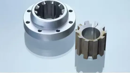
Face milling is often used to establish a flat datum before drilling, slotting, or contour machining.
What Information Should You Provide Before Requesting a Quote?
When requesting CNC machining services that include face milling, provide:
- A 3D CAD file and a 2D drawing showing critical dimensions, tolerances, and datums
- Material grade, heat-treatment condition, and stock form
- Quantity, target lead time, and batch requirements
- The surfaces requiring face milling and their flatness, parallelism, and surface roughness requirements
- Cosmetic, sealing, and mating surfaces, as well as areas where clamp marks are not permitted
- Requirements for subsequent anodizing, coating, grinding, assembly, or inspection
The more complete the information, the easier it is for a supplier to evaluate the workholding method, machining allowance, tooling strategy, and inspection plan—and to provide a more reliable quotation and lead time.
Frequently Asked Questions
Can Face Milling Replace Grinding?
Not always. Face milling can produce good flatness and surface quality, but grinding, lapping, or another finishing process may still be required when a drawing specifies very tight flatness, parallelism, or surface roughness. The decision should be based on the drawing requirements and the verified capability of the selected process.
Must the Face Mill Diameter Be Larger Than the Workpiece Width?
No. A larger cutter may cover the surface in fewer passes, but it also places greater demands on spindle power, rigidity, and available clearance. A smaller cutter can machine a wide surface using multiple overlapping passes. Cutter diameter should be selected according to the workpiece width, machine capability, toolpath, and surface requirements.
Should Face Milling Use Climb Milling or Conventional Milling?
Modern CNC equipment typically favors climb milling because it can provide stable cutting and a good surface finish under suitable machine and tooling conditions. However, manual machines with backlash, workpieces with mill scale or casting skin, and interrupted engagement require evaluation by a manufacturing engineer. The choice should not be made without considering the condition of the machine and workpiece.
Why Do Tool Marks or Steps Appear After Face Milling?
Common causes include axial tool runout, inconsistent insert seating height, incorrect spindle-to-table tram, workpiece or cutter vibration, improper overlap between toolpaths, and chip recutting. Check the machine geometry and insert installation before adjusting cutting parameters.
Conclusion
Face milling may appear to be a basic flat-surface operation, but consistent results depend on coordinated control of the cutter, parameters, workholding, toolpath, and inspection. General-purpose face milling, high-feed milling, heavy-duty cutting, and finishing each serve different objectives. Efficiency cannot be achieved simply by increasing spindle speed or feed.
If you need help planning face milling or a complete CNC milling process for custom parts, provide your 3D CAD file, 2D drawing, material, quantity, critical tolerances, surface requirements, and target lead time when requesting a quote. Complete information helps the engineering team evaluate manufacturability, the machining strategy, and inspection requirements.